Introduction
In the complex landscape of water treatment, shallow sand and industrial sand media filters have emerged as pivotal components. Shallow sand filters, characterized by their relatively thin layer of sand media, typically ranging from 15 to 30 cm, are designed for efficient removal of suspended solids and turbidity. Their compact nature makes them an attractive option for applications where space is at a premium.
Industrial sand media filters, on the other hand, are engineered to handle the rigorous demands of industrial processes. They utilize high – quality industrial – grade sand and are built to withstand large volumes of water and harsh contaminants. These filters play a crucial role in safeguarding downstream equipment, such as pumps, heat exchangers, and membranes, by preventing the ingress of particulate matter that could cause fouling, corrosion, or mechanical damage. By ensuring the supply of clean water, they contribute to the smooth operation and longevity of industrial systems.
Advantages & Features
2.1 Compact Design
Their shallow media layer results in a smaller footprint, saving space in installation areas. This makes them ideal for facilities with limited space, such as small factories, commercial buildings, or mobile treatment units.
2.2 Quick Backwashing
Shallow sand filters require shorter backwash cycles compared to deep-bed filters. The thin media layer allows for faster removal of accumulated contaminants, reducing downtime and ensuring continuous operation. Industrial variants often have automated backwash systems for added efficiency.
2.3 Cost-Effective
The use of sand as the primary media, which is abundant and affordable, lowers initial and replacement costs. Additionally, their simple structure minimizes maintenance expenses, making them a budget-friendly choice for many applications.
2.4 High Flow Rates
Industrial sand media filters are engineered to handle high flow rates, suitable for large-scale industrial processes. They efficiently process large volumes of water without significant pressure drops, ensuring consistent performance.
2.5 Versatile Media Options
While sand is the main media, these filters can incorporate other materials like anthracite or gravel in layered configurations to enhance filtration efficiency for specific contaminants, such as finer particles or organic matter.
Structure Specification
3.1 Filter Vessel
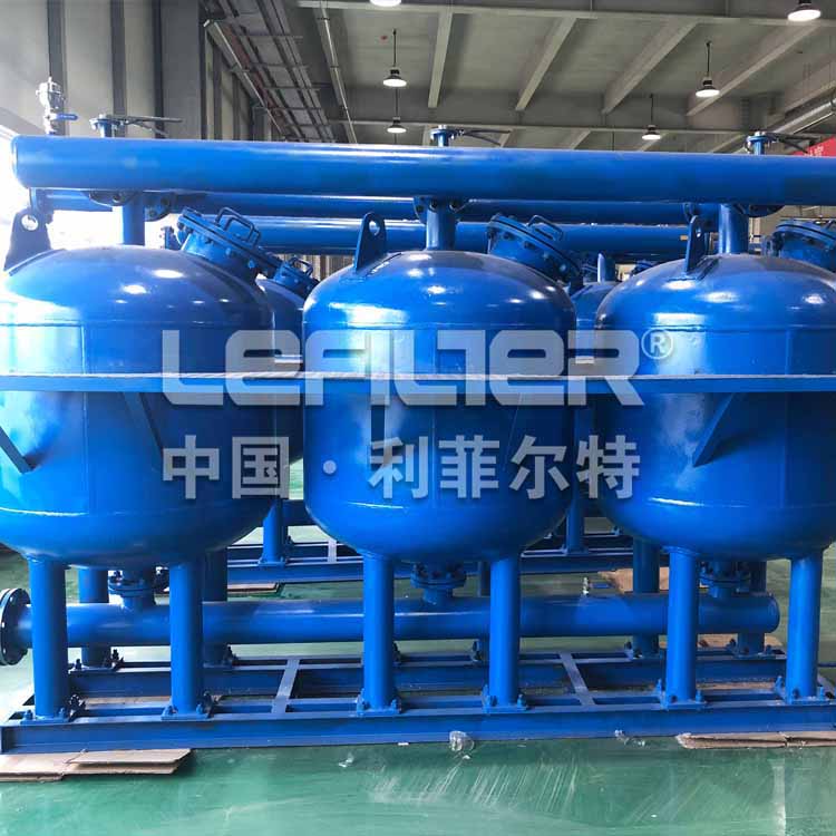
The filter vessel serves as the main housing for the filter media and the water being treated. For shallow sand filters, vessels are often constructed from materials like fiberglass – reinforced plastic (FRP) due to their corrosion resistance and lightweight nature. In industrial applications, where higher pressures and more corrosive environments may be encountered, carbon steel with a corrosion – resistant lining or stainless steel is commonly used. The vessel can be either vertical or horizontal. Vertical vessels are more prevalent in smaller – scale applications, as they offer a more space – efficient solution. Horizontal vessels, on the other hand, are preferred for larger flow rates as they can provide a larger surface area for filtration. The size of the vessel is determined by factors such as the required flow rate, the type of media used, and the expected filter run time between backwashes.
3.2 Sand Media
Shallow filters typically use fine to medium – sized sand with a particle diameter ranging from 0.4 to 1.2 mm. This size range is effective in capturing a wide range of suspended particles. Industrial sand, on the other hand, is carefully graded to ensure durability and uniformity. It can withstand the abrasive forces and high – volume flows associated with industrial processes. The thickness of the sand media layer in shallow filters is usually 15 – 30 cm, while in industrial sand filters, it can range from 30 cm to over 1 meter, depending on the specific application and filtration requirements.
3.3 Support Layer
Beneath the sand media, a support layer of gravel is placed. The gravel, with a particle size ranging from 2 to 10 mm, serves two main functions. Firstly, it provides structural support to the sand media, preventing it from being washed out during the filtration and backwashing processes. Secondly, it helps in evenly distributing the water across the filter bed. This ensures that the entire surface area of the sand media is utilized effectively during filtration, maximizing the removal of contaminants.
3.4 Distribution/Collection Systems
An inlet distribution system is installed at the top of the filter vessel. This system, which can consist of perforated pipes, spray nozzles, or weir troughs, is responsible for evenly spreading the incoming water over the surface of the sand media. This even distribution is crucial for preventing channeling, where water may flow through the filter bed in a non – uniform manner, reducing filtration efficiency. At the bottom of the vessel, an outlet collection system, often in the form of a network of perforated pipes or a false bottom with slots, is used to gather the filtered water. The collection system is designed to retain the sand media while allowing the clean water to pass through and be directed out of the filter.
3.5 Control System
A control system is integral to the operation of these filters. It includes valves for regulating the flow of water during filtration and backwashing. In shallow sand filters, these valves can be manually operated in some cases, especially in small – scale applications. However, in industrial sand filters, automated control systems are more common. These systems, often based on programmable logic controllers (PLCs), can monitor parameters such as pressure differentials across the filter bed. When the pressure differential reaches a pre – set value, indicating that the filter is becoming clogged, the control system automatically initiates the backwashing process. This automation ensures consistent and reliable operation, reducing the need for manual intervention and minimizing the risk of human error.
Working Principle
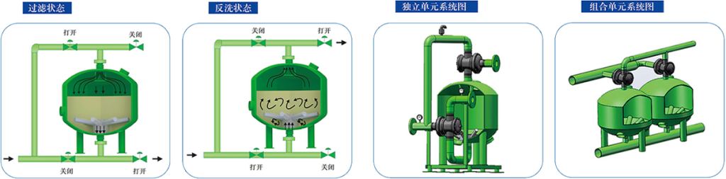
During filtration, water enters the vessel and flows downward through the sand media. Suspended particles are trapped by mechanical straining, adsorption, and interception within the sand pores. The filtered water passes through the support layer and is collected by the underdrain system for discharge.
As contaminants accumulate, the pressure differential across the filter increases. When it reaches a set threshold (typically 0.5-1.0 bar), backwashing is initiated. Backwash water flows upward through the media, expanding the sand bed and dislodging trapped particles. The dirty water is flushed out through a waste valve. After backwashing, a rinse cycle settles the media, and filtration resumes.
Application
5.1 Industrial Pre-Treatment
Used in manufacturing, power plants, and refineries to pre-treat raw water before it enters boilers, cooling towers, or process lines, preventing scale and equipment damage.
5.2 Municipal Water Treatment
Applied in small to medium-sized water plants for removing turbidity and sediments from surface water or groundwater, improving water clarity before disinfection.
5.3 Commercial Facilities
Installed in hotels, shopping malls, and hospitals to treat water for HVAC systems, swimming pools, and general use, ensuring clean water supply.
5.4 Agriculture and Irrigation
Filters irrigation water to remove sand, silt, and debris, protecting drip systems and sprinklers from clogging, and enhancing crop yield.
5.5 Wastewater Treatment
Used as a primary treatment step in industrial wastewater processing to reduce suspended solids before further treatment, easing the load on downstream processes.